Showing posts with label physical computing. Show all posts

Tuesday, December 1, 2009

Physical Computing Midterm: Media Controller; "Pancake"


The "Pancake"


Again, a bit late on the delivery of this one.  Apologies to those waiting with bated breath....

For our Physical Computing midterm, we were split into groups and asked to create a media controller of our own devising.  No limits or requirements were put in place, except that the controller would be a physical interface to the arduino, and would controller some external media device.  I was teamed with the wonderful Amy Chien and Chris Alden, and the three of us came to the conclusion that we'd like to build something of an electronic musical instrument.

To start things off, we brainstormed about possible ideas for the media controller's interface.  However, we came up with so many cool ideas that we almost immediately decided that we'd like to do multiple interfaces.  This worked its way into a concept for a modular music table, that would be split into various pieces, and allow three individuals to collaborate using three different interfaces. 


Hauling wood.

The first step we took was to construct the table surface.  We procured two large pieces of ply wood, and cut them into identical circles.  One circle was the table itself, while the other circle was cut into pieces for us to build the interface modules.  Each of us took on one of the modules, and each module used a different physical interface.  The three interfaces were wind based, pressure based, and a conductive sequencer.


All three interfaces.

Once we had completed and tested the three interfaces, we brought them together to the table, and unified them into a single instrument.  Each interface had its own arduino, which were then collectively wired into a labtop via a USB hub.  Once all three arduinos were recognized on the computer, we then hooked them up to Max/MSP and created a patch that would listen for the serial values from each interface, and use them to control tonal output.


The pressure pad controlled pitch bending, the wind interfaces controlled the speed of the tone playback, and the sequencer controlled the notes being played over the loop.  Once the patch was loaded, all three interfaces could be used simultaneously to control the computer's sonic output.  You can see a demo of one of our classmates joining us in trying out the interface above.


Finally, we presented our project in class.  Here you can see a brief clip of our presentation, which managed to go off without a hitch.  Midterm, complete. Go Pancake!

Monday, November 23, 2009

Physical Computing Week Eight Lab: Transistors and H-Bridge

Again, a bit late with this one, but better late than never.  In week eight of Physical Computing, we investigated the use of two slightly more complex devices:  the transistor and the h-bridge.


The transistor lab consisted of attaching a transistor to a small motor, and controlling the voltage output to the motor via the transistor.  This differs from a typical input/output in that the transistor can accept a far higher voltage than the arduino microcontroller's 5 volt power supply.  As such, the arduino can still be used to control a device that requires a much higher voltage.  The circuit with the motor can be seen above, while a video of the on/off control can be seen below.


The h-bridge lab consisted of using an integrated circuit known as an h-bridge to control the direction of current.  Put differently:  the motor from the first lab will run in different directions, depending on which way it is wired in the circuit.  The h-bridge allows us to select which direction of current we prefer, thus allowing for a single wiring scheme for the motor, but allowing us to decide (via a switch) which way we'd like the motor to rotate.  You can see a photo of the circuit above (the h-bridge is in the center), with a video of the bi-directional motor control below.


Wednesday, October 28, 2009

Physical Computing: Reaction To Visual Intelligence


Donald Hoffman's "Visual Intelligence" manages to take a relatively conventional concept (that our brain "tricks" us into perceiving much of what we deem "real"), and illustrates it through the novel venue of amputees.  By using the amputees' sensation of phantom limbs, Hoffman creates a tangible and realistic illustration of the disconnect between the physical and the mental world.

While Hoffman's examples do a great job at illustrating the concepts, the concepts themselves aren't exactly novel.  It's a well known fact of many simple schoolyard tricks that the brain can be easily tricked into misperceiving "reality".  Watching movies, smelling one thing while eating another, combining hot and cold sensations - all of these things can allow us to trick our nervous system into perceiving things that aren't "really" there.

In the end, this fact is obvious, but perhaps overlooked because it is so common:  the best thing we can do moving forward is to try and consider how we are really perceiving the world around us, and enlist this as we make choices in design.

Tuesday, October 27, 2009

Physical Computing Week Seven Lab: Multiple Serial Output

Building on last week's serial lab, this week took the same principles and applied them to multiple, rather than a single, serial data source.  In this case we took a circuit containing two analog and one digital sensor, and sent the output to a Processing script.


Here's a picture of the circuit - as you can see, there are two analog inputs (the potentiometers) and one digital input (the push button).  As was noted in the lab, this set of inputs represents the same inputs as a typical one button mouse.


As such, the inputs were used to control a circle on screen, with the push button turning the circle on and off.  You can see this control at work in the video above.


After getting the script working with a streaming serial input, we then rewrote the arduino side to wait for a handshake before it started sending data.  Once it received the handshake, it would send only one set of data, until it received a request for another set.  This serial behavior can be seen in the video above.


As mentioned at the top of the lab, the principles put to work here are very similar to the ones from last week's lab, but simply expanded to allow for multiple inputs.  This, in turn, allows us to use the Arduino's serial output in a far more versatile and productive manner.

Tuesday, October 20, 2009

Physical Computing: Real World Technical Observations

This week we were asked to go into the "real world" and observe people interacting with devices, and see how it met with our expectations.  I did just that, but unfortunately had very little to report in terms of results:  Everywhere that I went, people seemed to use devices or interfaces exactly as expected.

I spent some time near an ATM, by the entrances to some buildings, and near some subway metrocard machines.  In all cases, it seemed that the users knew how to use the devices on hand, and simply went through the motions, often almost intuitively.  There are two explanations that I can attribute this two in relation to last week's readings.  

First, it may simply be that people are smarter than the "bad design" critics give them credit for.  Put differently: just because something is poorly designed doesn't mean it's unusable.  It's just that it's sort of a hassle, but that people are adept enough to figure it out.  Take the case of a PC:  I used Windows perfectly well for years.  Now that I use OS X, I'm far happier, but my ability to function hasn't particularly changed.

The second explanation is that it's simply a case of learned behavior:  in a city like New York, people tend to have routines and typical day to day actions.  It may simply be that the people I observed have overcome poor design because they've become so accustomed to it - now they simply function as normal, and envelop the poor design in their routine.

I think the reality is that it's probably some of both:  Very few poor designs are unfathomable, but they could be somewhat challenging at first.  However, after the 100th time using a door or an ATM, very few functional humans are going to keep making the same mistake.  That being said, the reality is that if there were more, better design, it might simply make people's lives easier.  This might in turn lead to happier people, and then - who knows!

Physical Computing Week Six Lab: Serial Output

Through no fault of ITP's, this week's lab was perhaps the most redundant task I've undertaken since starting the program.  This is largely due to the fact that when I started working at Dolby Laboratories, my first sizable task was to write almost the entire software stack for serial communciation on the Dolby Digital Cinema system.  As such, doing so in a basic manner on the arduino/processing platform ended up being pretty trivial.  That being said, it was fun to see it working, and to discover that processing and Dolby use the same serial back end libraries - RXTX!


Because of my strong familiarity with the material, I designed a relatively simple circuit employing a potentiometer to send analog data over the serial port.


Doing a read on this data was also relatively straightforward, allowing it to be piped into a graph in processing, which can be seen above.


Yay!  Serial communication!

Physical Computing: Stupid Pet Trick

With the knowledge acquired thus far, we were enlisted to create a "Stupid Pet Trick" for Physical Computing.  In short, this meant creating a novel, simple device that enlisted out knowledge of analog and digital inputs and outputs in a hopefully entertaining.  In my case, I decided to take the assignment quite literally, and design an interactive cat toy.


The toy consists of two pieces:  a tennis ball on a spring, and a laser pointer mounted on a servo.  Once the program is initialized, the servo is driven by data coming from a flex sensor embedded in the tennis ball.  In this way, the play of one cat (with the tennis ball), will drive the entertainment of another (with the laser pointer).  In short, it's a low maintenance way to have the animals keep each other busy.


I embedded the tennis ball and spring in a wooden platform for stability, and fed a flex sensor up into the spring.  That way, when the spring bent, so did the flex sensor.  I routed a wire conduit out of the wood so that the wires would be hidden, and then sealed them in with a glue gun.

The laser mounted on the servo was a bit more of a "hack job", employing twist ties and a free Flaming Lips laser pointer.  However, in the end it worked out quite well, with the on/off button controlled by another twist tie.

The circuit itself was actually quite simple, needing only one input and one output for the flex sensor and servo, respectively.  What's more, it worked quite nicely with the spring easily driving the servo.  

 Perhaps the only drawback was that as a sketch of a device, I kept the two pieces quite close together.  This resulted in the two components being far too close together to allow for "real world" testing without the two pieces distracting the animals from "their" side of the toy.

Tuesday, October 13, 2009

Reactions To "Attractive Things Work Better" and "The Design Of Everyday Things"


This week in Physical Computing we were asked to read two pieces,  both by Don Norman.  The two pieces provided contrast to each other, in that the first, "The Design Of Everyday Things" is a chapter from Norman's original book focusing on usability, while the second is an essay attempting to amend some of his original conclusions and take aesthetics and emotion under consideration.


While both readings are interesting, by in large their conclusions both seem to exist extremely squarely in the realm of common sense.  Perhaps this is because the writings are close to two decades old, and it is certainly true that capable and aesthetically pleasing designs have become much more mainstream in the past ten years.


In the first piece, Norman makes a strong case for utilitarian designs, and the need to consider usability in deployment.  In the second piece, he responds to his own writing, by conceding that aesthetics can have an equal importance to usability when designing the optimal device.


That being said, many of Norman's examples seem trite, or perhaps from another age.  The tasks or devices that he cites as being challenges are simply things that most adults today know how to deal with.  The "blinking clock on the VCR" is a joke rooted in the 80's, and with good reason; it's simply no longer an issue.


Norman's writings may have had poignancy and relevance ten years ago, but today they serve to do something different.  They are illustrative of the advances that have been made in design in the mainstream, and just how prevalent they are.  Here's hoping the trend continues.

Monday, October 5, 2009

A Reaction To "Design Meets Disability"

This week's reading for Physical Computing explored the gap between the worlds of design and engineering, focusing specifically on the realm of devices made to assist the disabled.  The article contained a wide range of insights about this largely engineering based industry and its seeming disconnect from the world of design and aesthetics.  However, the portion that resonated with me most strikingly was the greater problem of separation of industries.  

In today's world, it seems that there are often very striking lines drawn between industries, resulting in the undesirable result of poor implementation, reduction and usability.  This is clearly exemplified in the article in relation to devices such as wheel chairs, prostheses, and hearing aids.  However, this is just one example of a gap that needs to be bridged.  Throughout day to day life, we see and use devices and interfaces that are hindered by the fact that they were engineered, and never designed.  

Thankfully, this is a problem that is slowly being addressed by many companies, and hopefully is the reason that many of us are at ITP:  To gain insight, learn from others' experiences, and create devices that encompass a wider array of perspectives and insights.

Physical Computing: Week Four Lab

In week four, Physical Computing turned to using our analog output to work creating productive output products.  This included two labs, creating output in two forms.  The first was a servo lab, which took an analog input and mapped it to the physical movement of a servo.  The second was a tone lab, which took analog input and mapped it to the output of a small speaker.  Both demonstrated that an analog sensor can easily be used to create tangible output effects.


In the first lab, we wired a circuit to include an analog sensor and a servo.  In this photo we can see this circuiy implemented, with a flex sensor in place to control the servo.


Once the circuit was completed, a simple upload of the lab's arduino program yielded the behavior seen in the video above. Either a manual pulsing or the arduino servo library could be used, and the same behavior resulted. In short, the flex sensor's analog output controls the position of the servo.


The second lab followed a similar concept, but instead used the sensor to control tone on a speaker. I chose to use a potentiometer for my control, so that dialing it would control pitch. This circuit can be see above.


Once wired, this circuit also required a small arduino program that would map the analog inputs to an analog output value for the speaker. In the video above, the potentiometer is being moved, and the resulting speaker tone changes in turn.

Thursday, October 1, 2009

A Reaction To "The Bandwidth Of Consciousness"

In taking on this week's reading, "The Bandwidth Of Consciousness", I have to say that I'm a bit flummoxed on a number of counts.  Most notably, the fact that the author believes that the correlation between bit rates and human thought and bandwidth is even a reasonable one.  If I look at an extremely high resolution image (say, 100 MB), am I suddenly consuming data at that "bit rate"?  More imporantly, say the color depth of that image increases so that it's now 200 MB in size.  Am I now consuming even more data?  The prospect is silly, because the fact of the matter is that humans don't consume data as "bits", and an attempt to illustrate otherwise is a lost cause.  For another example, think of audio:  recorded audio has a bit rate that could potentially indicate "bandwidth", but then live audio has an infinite "bit rate".  If I listen to a live violin, is my bandwidth consumption infinite?  However, even more ridiculous is the concept as a whole:  the idea that you can take the input to the human nervous system and in any way quantify it is simply a principle that I don't see as viable.  While it's certainly interesting to see scientists attempting to pursue explanation in this manner, at the end of the day I can't really see that it yields very much value or insight to the reality of the situation.

Tuesday, September 29, 2009

Physical Computing: Week Three Lab

This week's Physical Computing Lab consisted of learning some basics about electricity.  A lot of it felt like review from PSSC Physics, but maybe that's just me.  That being said, I also dug in and did some soldering for the first time in about a year, so that was cool.  I also learned a thing or two about my multimeter's sensitivity, which is apparently one decimal place shorter than the one owned by Tom Igoe.  Read on for all the glorious excitement.


The first bit of the lab involved getting a DC power source connected to the bread board.  While it technically could have been achieved without soldering, I decided that messing with a power supply was silly-slash-stupid.  So, I put my soldering chops to work and soldered the power jack, as seen above.


Once the power supply was attached via the power jack, we setup a small circuit involving an LED and a voltage regulator.  In this photo you can see the voltage meter keeping the voltage steady at 5 DC volts.  This setup would be the testbed for our various voltage and amperage experiments.


In the above two photos you can see some voltage tests on both the resistor and the LED. You can see that the two have different voltage consumptions, but more importantly that the summation of the two is equal to the five volts being put out by the voltage regulator.

Our next step was to set up two LED's in series.  As you can see from this photo, the LED's lit, but to a lesser extent.  From the voltage readings in these photos we can see that since the LED's were forced to share voltage, each consumed less power than the single LED setup.  This is a result of the series circuit. When I attempted to use three LED's, they simply did not light due to lack of voltage.


The next step involved a similar setup, but in parallel. In this case the LED's have a uniform voltage of 1.95. This reading can be seen here on only one LED, but was the same for all three.


Next I made an attempt to measure amperage, and was met with no reading. In fact, I later determined that the setup was working (as evidenced by the lit LED), but that my multimeter was simply not on a sensitive enough setting.


The final step was to use a potentiometer to limit voltage to the LED.  In the above photos we can see the potentiometer in three positions (on, half, and off) and the resulting voltages.  This is a clear illustration of the potentiometer acting as a voltage divider.  You can also check out the video below for a "live action" take on this electrical phenomena.


Potentiometer Controlling Variable Voltage On An LED from Hippies Are Dead on Vimeo.

Tuesday, September 22, 2009

Physical Computing: Fantasy Device - "Anywhere Box"

The internet has largely transformed data usage and consumption into a location-free activity.  Videos can be streamed, documents can be shared, music downloaded, and conversations had across oceans.  What the "Anywhere Box" attempts to do is take this principle and apply it to physical objects.  By providing the user with a physical interface to a remote box, the anywhere box turns the location of an object into an irrelevant issue, much like email servers or web space do with digital data today.

This, of course, first begs the question of what one might keep in the Anywhere Box.  Perhaps the most obvious answer is those things that people always want to have access to, but are continuously misplacing:  keys, wallets, cell phones, and the like.  However, even more interesting is the possibility of having access to more valuable possessions at a moments notice:  family jewelry, birth certificates, large amounts of cash, etc.

The box consists of two pieces:  the end user "frame", and the box's "home" location.  Much like a safety deposit box, the home location is highly secured to allow for complete ease of mind.  However, it is even far more important to note that the location of the home box is irrelevant, since it can be accessed by the user at any time via their frame.  This means that the box storage facilities could be underground, in space, or any other location that might prove convenient.


The user's frame takes on a guise similar to that of the tablet PC:  it a flat computer-based interface consisting of a screen and a small number of buttons for security and power purposes.  Once the user powers on the frame and completes security scanning (see below), the frame "activates" and provides access to the user's Anywhere Box.


The box itself would be rather modest in size, to allow for easy access from the frame.  It would share the two dimensional sizing of the frame, and a depth of no more than one foot.  This would allow all the contents to be easily accessible, and all visible at one time through the frame.  The box would be equipped with a sister frame (not visible to the user) that would allow the frame to make the connection and provide access to the box.


Security is the primary concern of such a device, and as such would provide a wide range of contingencies to verify the user's identity as follows:
  • The frame would feature a voice, retinal and fingerprint scanner, all of which would be required in unison to access the box. This would allow for complete biometric identification, and moreover almost infallible security.
  • Once these three tests had been passed, the frame would optionally require a numeric code, for users that wanted an extra layer of security.
  • The frame would be irreversibly paired with the home box.  If the frame is destroyed, there would be no other way to connect to the box, aside from physically being in its presence.  In this case the user would have to contact the manufacturer to get access to a new box and frame.  This would ensure against any sort of outside hacking or network based breaches, as the hardware would be linked outside of network protocols.

 The Anywhere Box provides a number of challenges, not the least of which are physics and reality.  It would require something in the nature of a teleporter or a worm hole.  Not only that, but once the connection was established, there's still the issue of the physical relationship between the inside of the box and the outside world.  If one turns box upside down, do its contents spill out?  If it's filled with water, can it spill?  These questions illustrate the unreality of the Anywhere Box.

However, the Anywhere Box also investigates the nature of data in the 21st century through a different lens.  Can we shift our data paradigm to apply to all objects?  If an object is accessible everywhere does it become more or less valuable?  If you had access to your most important objects at all times, how would your life change?  Would an always-secure personal safety deposit box obviate the need for banks?  The Anywhere Box brings about all these questions, and illustrates the remaining necessity of physical objects in a digital age.

Physical Computing: Week Two Lab

Week two of physical computing sees us engaging with analog input devices, and using that input to drive an output.  Specifically, we were asked to use a range of analog input devices to drive an LED.  I chose to keep it simple and use a potentiometer and a photo sensor to drive a simple one LED setup.  Not exactly intricate, but definitely to the point and capturing the essence of the idea.


The first task was to wire a potentiometer to the breadboard.  In this picture you can see the potentiometer wired and connected to analog I/O zero, in this case as an input. After adding the potentiometer, I then added the LED to digital I/O nine, and set this port to output mode. You can see the LED in this photo as well, ready to act as a reflection of the potentiometer's position.


Using the provided lab code, the setup was validated, and the potentiometer used to control the LED. This can be seen in the video above.


Following the use of the potentiometer, we were encouraged to use another analog sensor to deliver a signal to the LED. In this case I chose a photosensor that comes with the ITP materials kit. At first (as can be seen in the above video), the sensor gave me passable, but suboptimal, results.


I discovered this was due to the fact that I was using an inappropriate resistor, and not massaging my input data in any way. By switching the resistor to more appropriately match the rating on the photosensor, and furthermore mapping top and bottom data input, I managed to coax the LED into reacting more smoothly to the input.

While this week's lab was certainly interesting, it seems like it could be easily combined with week one's lab.  The principles are largely the same, and making the jump from digital to analog input isn't a large one.  That being said, there is far more potential for experimentation with analog sensors that I failed to take advantage of:  I'm planning on kicking that into gear with next week's Stupid Pet Trick.

Tuesday, September 15, 2009

Physical Computing: Week One Lab

Week one of Physical Computing brought on two labs that were both largely associated with familiarizing ourselves with the environment we'll be working in all semester.  Specifically bread boards, the Arduino microprocessor, and basic circuits.  As such, the labs involved more hammering out the basics than they did pushing the boundaries.  That being said, with the addition of my Applications presentation this week, I wasn't exactly heartbroken to have PComp go easy on my creative side.  

The first section of the lab consisted of familiarizing ourselves with the breadboards from our tool kit.  While it's a pretty basic concept, it's still worth going over and comprehending.  Basic points are as follows:
  • The bread board consists of two parts: powered columns and isolated rows
  • Each powered column is connected along the length of the board on the left and right sides.  If these are connected to a power source and board, they then provide power to use in circuits.
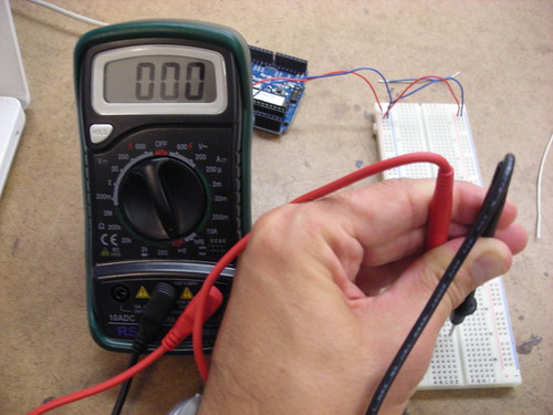
  • The isolated rows go from top to bottom in the middle of the board, and are further isolated by a divider down the middle.  This means for each row you have two sides that are isolated for use in a circuit.  The photo above illustrates a multimeter validating the continuity of a single row.
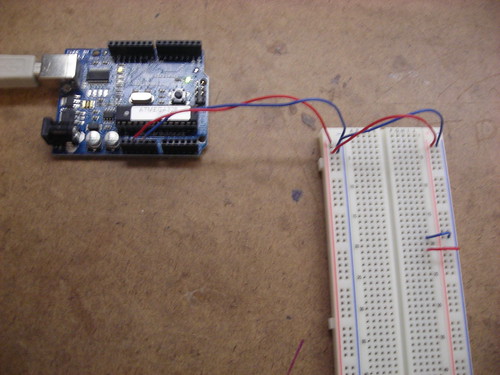
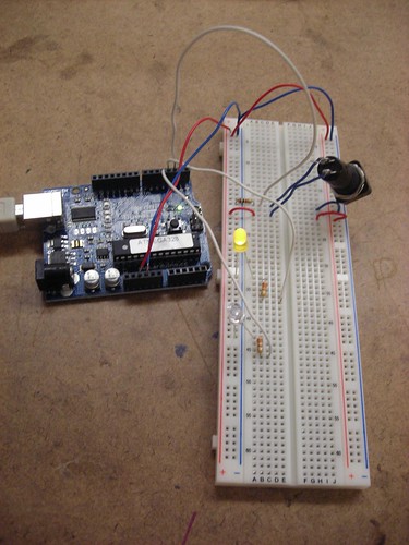
The next step was to actually power the board.  This requires a 5 volt power supply and a ground.  Above, you can see breadboard prepared and powered via the Arduino.  Note that I've also wired two rows to use the power source: one row is a ground row, the other is a powered row.

 
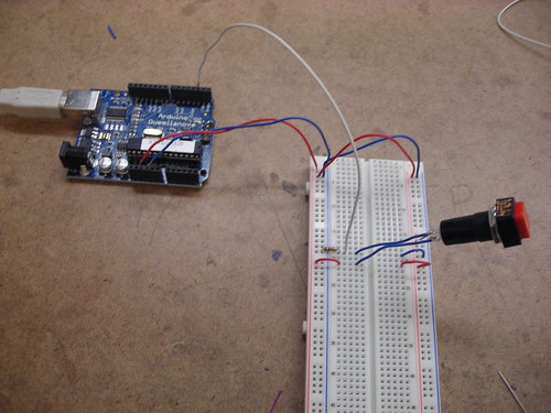
Once the board was powered, the next step was to add a switch.  I decided to use a standard retail switch, and wire it to the left side of the board.  The switch was connected (via the white cable, above) to a digital input of the Arduino, which would allow us to programatically track the switch's state.  This required using two rows, and the addition of a resistor.  The addition of the resistor ensures that the switches state will be reflected over the digital input wire, rather than just disappearing over the ground.
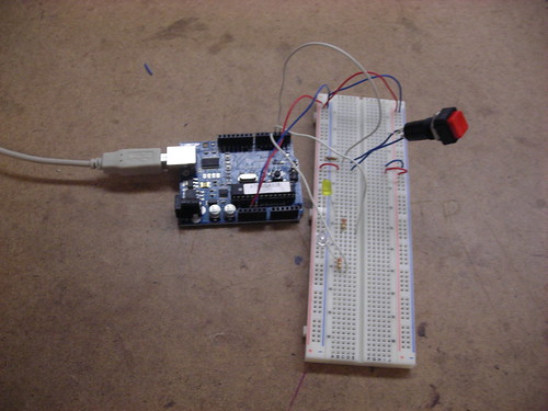
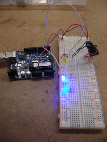
With the switch implemented, it was time to add LEDs to the board.  The Arduino program would track the state of the switch, and modulate the LEDs accordingly.  Above you can see a picture of the LEDs wired to the Arduino's digital outputs.  The resistors in place assure a minimal load on the LEDs in order to increase their life.

Finally, the setup was put to work:  I compiled and uploaded the program from the lab to the Arduino, and proceded to enable it.  Depending on the state of the switch, a different LED would be lit.  You can see the two states above, and a video of the working mechanism below.


Once the basic switch setup was complete, we were entreated to contemplate other possible applications of basic digital I/O, particularly with regard to a combination lock.  Upon considering this, most of my ideas drifted into the range of abstract or shape based locks.  While most combination locks in the real world tend to be based around numeric key pads, it seems that one could be constructed based more soundly around interacting with a grid of switches that were either uniform, or based on a wide array of shapes and sizes.  This would have the advantage of being more secure due to its abstract and spatial nature, and also being easier to remember for individuals who are already inundated with a large number of numeric codes in their lives.  One example of this implementation that already exists in the digital world is the gesture based security in the Android mobile OS.  However, there's no reason this same concept couldn't be applied to physical locks as well.

Sensor, Walk With Me


Today, as per our first Physical Computing assignment, I took the walk from ITP uptown to pick up my laundry in Chelsea.  Here's a log of some of the more notable sensors I saw in my environment.

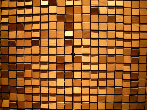
The walk started as I left ITP and walked past the "wooden mirror" - that dot in the middle is a camera!  Photo sensor to the max!
 
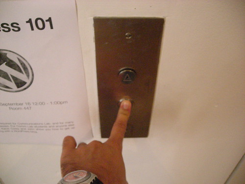
I walked on towards the elevator and interacted with a sensor on the elevator button.  Once I got inside, the button for downstairs had already been pushed, so I didn't get two sensors in one interaction...

 
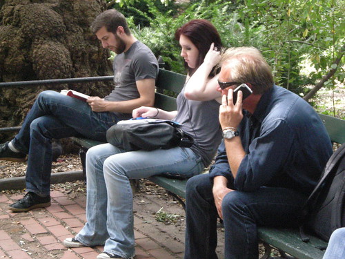
From there I walked into Washington Square Park, where I saw this woman tapping away on the sensors in her computer's keyboard.
Across the way, this guy was talking on his phone - the microphone is a sensor measuring the output of his voice.
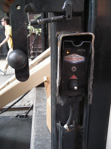
Soon after I walked past some folks loading a truck with a lift.  They didn't want to be in the photo, so I just snagged a picture of this sensor, which caused the lift to move up and down.
This woman was a tad more accommodating, and cracked up as I took a picture of her texting away - and more importantly, pressing the sensors of the buttons on her phone!
This guy was taking a picture of his friends on the street - talk about sensors:  photo sensor, distance sensor, sensor on the camera's button - techno overload!
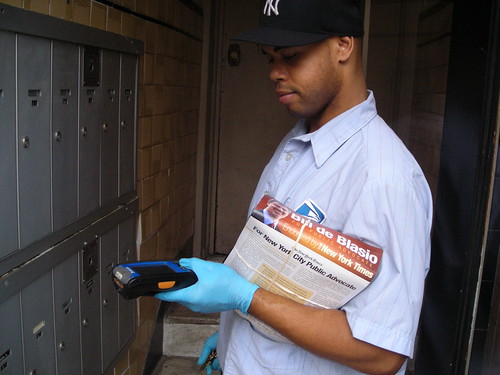
This postal worker had a fancy-schmancy device with a touch screen sensor, and he was kind enough to let me snap a shot of him using it.
 
Debateable as to whether it's "really" a sensor, but it seemed like maybe these bells could qualify as a sensor to the door's motion.

 
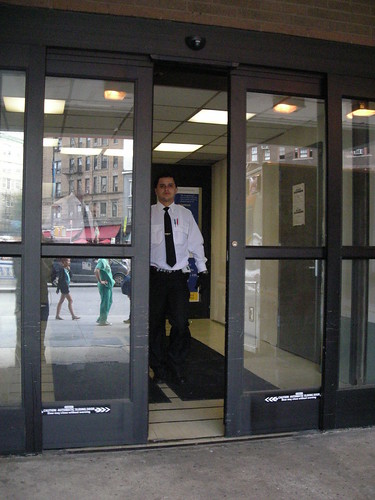
At St. Vincent's Hospital, the ER doors were equipped with motion sensors to open at a moment's notice.

 
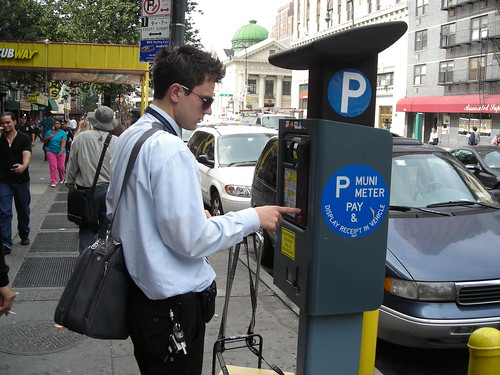
Meanwhile, New York's new parking meter slash computers provided this guy with a satisfying button press.

 
This restaurant employee uses a touch screen sensor all day, and is damned excited about it!

 
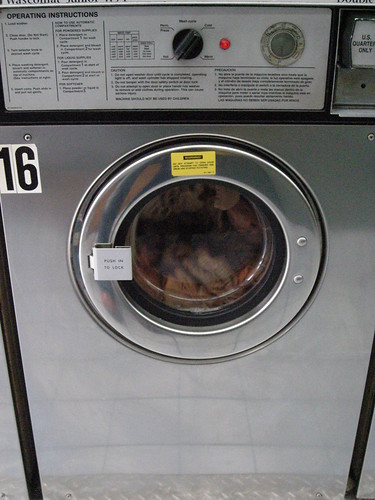
Finally, I arrived to pick up my laundry and noticed this load in progress: it's using a sensor to measure water levels before it starts to spin.

 
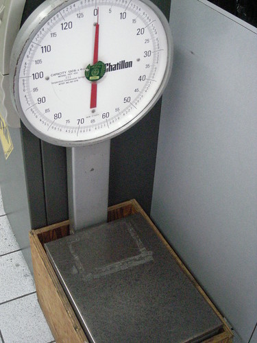
This scale is a sensor for laundry weight, and how much I'm going to be fleeced for keeping clean!

 
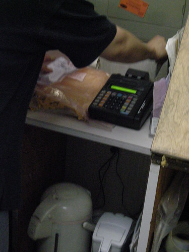
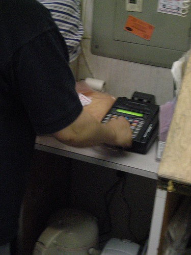
The credit card machine has two sensors:  one to read the magnetic stripe on the card...

 
...and the other to enter data via the key pad.

So I concluded my sensor walk:  fresh laundry in hand, and a new and unique perspective on my daily route home.