Tuesday, September 29, 2009

Physical Computing: Week Three Lab

This week's Physical Computing Lab consisted of learning some basics about electricity.  A lot of it felt like review from PSSC Physics, but maybe that's just me.  That being said, I also dug in and did some soldering for the first time in about a year, so that was cool.  I also learned a thing or two about my multimeter's sensitivity, which is apparently one decimal place shorter than the one owned by Tom Igoe.  Read on for all the glorious excitement.


The first bit of the lab involved getting a DC power source connected to the bread board.  While it technically could have been achieved without soldering, I decided that messing with a power supply was silly-slash-stupid.  So, I put my soldering chops to work and soldered the power jack, as seen above.


Once the power supply was attached via the power jack, we setup a small circuit involving an LED and a voltage regulator.  In this photo you can see the voltage meter keeping the voltage steady at 5 DC volts.  This setup would be the testbed for our various voltage and amperage experiments.


In the above two photos you can see some voltage tests on both the resistor and the LED. You can see that the two have different voltage consumptions, but more importantly that the summation of the two is equal to the five volts being put out by the voltage regulator.

Our next step was to set up two LED's in series.  As you can see from this photo, the LED's lit, but to a lesser extent.  From the voltage readings in these photos we can see that since the LED's were forced to share voltage, each consumed less power than the single LED setup.  This is a result of the series circuit. When I attempted to use three LED's, they simply did not light due to lack of voltage.


The next step involved a similar setup, but in parallel. In this case the LED's have a uniform voltage of 1.95. This reading can be seen here on only one LED, but was the same for all three.


Next I made an attempt to measure amperage, and was met with no reading. In fact, I later determined that the setup was working (as evidenced by the lit LED), but that my multimeter was simply not on a sensitive enough setting.


The final step was to use a potentiometer to limit voltage to the LED.  In the above photos we can see the potentiometer in three positions (on, half, and off) and the resulting voltages.  This is a clear illustration of the potentiometer acting as a voltage divider.  You can also check out the video below for a "live action" take on this electrical phenomena.


Potentiometer Controlling Variable Voltage On An LED from Hippies Are Dead on Vimeo.

Tuesday, September 22, 2009

Physical Computing: Fantasy Device - "Anywhere Box"

The internet has largely transformed data usage and consumption into a location-free activity.  Videos can be streamed, documents can be shared, music downloaded, and conversations had across oceans.  What the "Anywhere Box" attempts to do is take this principle and apply it to physical objects.  By providing the user with a physical interface to a remote box, the anywhere box turns the location of an object into an irrelevant issue, much like email servers or web space do with digital data today.

This, of course, first begs the question of what one might keep in the Anywhere Box.  Perhaps the most obvious answer is those things that people always want to have access to, but are continuously misplacing:  keys, wallets, cell phones, and the like.  However, even more interesting is the possibility of having access to more valuable possessions at a moments notice:  family jewelry, birth certificates, large amounts of cash, etc.

The box consists of two pieces:  the end user "frame", and the box's "home" location.  Much like a safety deposit box, the home location is highly secured to allow for complete ease of mind.  However, it is even far more important to note that the location of the home box is irrelevant, since it can be accessed by the user at any time via their frame.  This means that the box storage facilities could be underground, in space, or any other location that might prove convenient.


The user's frame takes on a guise similar to that of the tablet PC:  it a flat computer-based interface consisting of a screen and a small number of buttons for security and power purposes.  Once the user powers on the frame and completes security scanning (see below), the frame "activates" and provides access to the user's Anywhere Box.


The box itself would be rather modest in size, to allow for easy access from the frame.  It would share the two dimensional sizing of the frame, and a depth of no more than one foot.  This would allow all the contents to be easily accessible, and all visible at one time through the frame.  The box would be equipped with a sister frame (not visible to the user) that would allow the frame to make the connection and provide access to the box.


Security is the primary concern of such a device, and as such would provide a wide range of contingencies to verify the user's identity as follows:
  • The frame would feature a voice, retinal and fingerprint scanner, all of which would be required in unison to access the box. This would allow for complete biometric identification, and moreover almost infallible security.
  • Once these three tests had been passed, the frame would optionally require a numeric code, for users that wanted an extra layer of security.
  • The frame would be irreversibly paired with the home box.  If the frame is destroyed, there would be no other way to connect to the box, aside from physically being in its presence.  In this case the user would have to contact the manufacturer to get access to a new box and frame.  This would ensure against any sort of outside hacking or network based breaches, as the hardware would be linked outside of network protocols.

 The Anywhere Box provides a number of challenges, not the least of which are physics and reality.  It would require something in the nature of a teleporter or a worm hole.  Not only that, but once the connection was established, there's still the issue of the physical relationship between the inside of the box and the outside world.  If one turns box upside down, do its contents spill out?  If it's filled with water, can it spill?  These questions illustrate the unreality of the Anywhere Box.

However, the Anywhere Box also investigates the nature of data in the 21st century through a different lens.  Can we shift our data paradigm to apply to all objects?  If an object is accessible everywhere does it become more or less valuable?  If you had access to your most important objects at all times, how would your life change?  Would an always-secure personal safety deposit box obviate the need for banks?  The Anywhere Box brings about all these questions, and illustrates the remaining necessity of physical objects in a digital age.

Physical Computing: Week Two Lab

Week two of physical computing sees us engaging with analog input devices, and using that input to drive an output.  Specifically, we were asked to use a range of analog input devices to drive an LED.  I chose to keep it simple and use a potentiometer and a photo sensor to drive a simple one LED setup.  Not exactly intricate, but definitely to the point and capturing the essence of the idea.


The first task was to wire a potentiometer to the breadboard.  In this picture you can see the potentiometer wired and connected to analog I/O zero, in this case as an input. After adding the potentiometer, I then added the LED to digital I/O nine, and set this port to output mode. You can see the LED in this photo as well, ready to act as a reflection of the potentiometer's position.


Using the provided lab code, the setup was validated, and the potentiometer used to control the LED. This can be seen in the video above.


Following the use of the potentiometer, we were encouraged to use another analog sensor to deliver a signal to the LED. In this case I chose a photosensor that comes with the ITP materials kit. At first (as can be seen in the above video), the sensor gave me passable, but suboptimal, results.


I discovered this was due to the fact that I was using an inappropriate resistor, and not massaging my input data in any way. By switching the resistor to more appropriately match the rating on the photosensor, and furthermore mapping top and bottom data input, I managed to coax the LED into reacting more smoothly to the input.

While this week's lab was certainly interesting, it seems like it could be easily combined with week one's lab.  The principles are largely the same, and making the jump from digital to analog input isn't a large one.  That being said, there is far more potential for experimentation with analog sensors that I failed to take advantage of:  I'm planning on kicking that into gear with next week's Stupid Pet Trick.

Thursday, September 17, 2009

Solving A Rubik's Cube, or, Exercises In Extreme Boredom


After a number of vested attempts (both in the intellectual and physical world) to inspire myself in the art of solving a Rubik's cube, I found myself completely uninspired and apathetic about the task. Solving the Rubik's is an exercise in algorithm repetition and color matching, neither of which particularly appeal to me.

While it may not appeal to me, it was nonetheless a requirement of my class to demonstrate how the cube could be solved, and I needed a solution to that problem. As such, for those who are truly interested in solving the Rubik's, I offer up these fine options:
  • Watch the video above.  It's step 1 in an extremely (almost an hour!) lengthy tutorial.  I started nodding off on step 4,  but if this really interests you, the tutorial is exhaustive and complete.
  • Go to this link.  It's a Rubik's solver where you input your cube configuration, and it provides you with a solution.
  • If you're more code-minded, go here.  It's the source code for the above mentioned solver, and should lend coders an algorithmic insight into solving the cube.
While I realize these solutions might not be in the "spirit" of true Rubik's solvers, I think they do illustrate a greater point, which is that computers and technology enable us to do things faster and more quickly through the sharing of data.  What's more, the solver is a clear illustration of the ability of technology to eliminate repetitive, physical tasks.  This applies directly to visualization of data, which allows for an encapsulated and high level view of data that might otherwise be stupefying, or downright impossible to understand.

Tuesday, September 15, 2009

Physical Computing: Week One Lab

Week one of Physical Computing brought on two labs that were both largely associated with familiarizing ourselves with the environment we'll be working in all semester.  Specifically bread boards, the Arduino microprocessor, and basic circuits.  As such, the labs involved more hammering out the basics than they did pushing the boundaries.  That being said, with the addition of my Applications presentation this week, I wasn't exactly heartbroken to have PComp go easy on my creative side.  

The first section of the lab consisted of familiarizing ourselves with the breadboards from our tool kit.  While it's a pretty basic concept, it's still worth going over and comprehending.  Basic points are as follows:
  • The bread board consists of two parts: powered columns and isolated rows
  • Each powered column is connected along the length of the board on the left and right sides.  If these are connected to a power source and board, they then provide power to use in circuits.
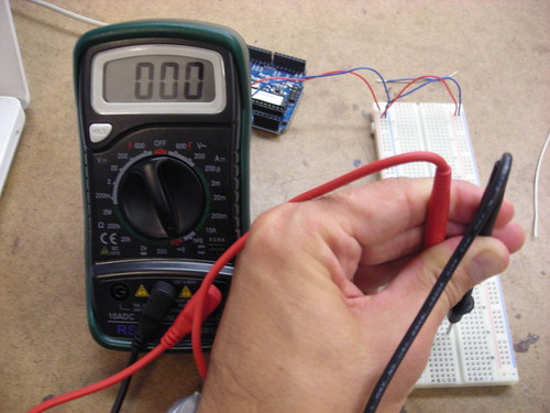
  • The isolated rows go from top to bottom in the middle of the board, and are further isolated by a divider down the middle.  This means for each row you have two sides that are isolated for use in a circuit.  The photo above illustrates a multimeter validating the continuity of a single row.
The next step was to actually power the board.  This requires a 5 volt power supply and a ground.  Above, you can see breadboard prepared and powered via the Arduino.  Note that I've also wired two rows to use the power source: one row is a ground row, the other is a powered row.

 
Once the board was powered, the next step was to add a switch.  I decided to use a standard retail switch, and wire it to the left side of the board.  The switch was connected (via the white cable, above) to a digital input of the Arduino, which would allow us to programatically track the switch's state.  This required using two rows, and the addition of a resistor.  The addition of the resistor ensures that the switches state will be reflected over the digital input wire, rather than just disappearing over the ground.
With the switch implemented, it was time to add LEDs to the board.  The Arduino program would track the state of the switch, and modulate the LEDs accordingly.  Above you can see a picture of the LEDs wired to the Arduino's digital outputs.  The resistors in place assure a minimal load on the LEDs in order to increase their life.

Finally, the setup was put to work:  I compiled and uploaded the program from the lab to the Arduino, and proceded to enable it.  Depending on the state of the switch, a different LED would be lit.  You can see the two states above, and a video of the working mechanism below.


Once the basic switch setup was complete, we were entreated to contemplate other possible applications of basic digital I/O, particularly with regard to a combination lock.  Upon considering this, most of my ideas drifted into the range of abstract or shape based locks.  While most combination locks in the real world tend to be based around numeric key pads, it seems that one could be constructed based more soundly around interacting with a grid of switches that were either uniform, or based on a wide array of shapes and sizes.  This would have the advantage of being more secure due to its abstract and spatial nature, and also being easier to remember for individuals who are already inundated with a large number of numeric codes in their lives.  One example of this implementation that already exists in the digital world is the gesture based security in the Android mobile OS.  However, there's no reason this same concept couldn't be applied to physical locks as well.

Sensor, Walk With Me


Today, as per our first Physical Computing assignment, I took the walk from ITP uptown to pick up my laundry in Chelsea.  Here's a log of some of the more notable sensors I saw in my environment.

The walk started as I left ITP and walked past the "wooden mirror" - that dot in the middle is a camera!  Photo sensor to the max!
 
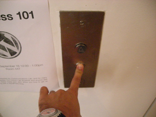
I walked on towards the elevator and interacted with a sensor on the elevator button.  Once I got inside, the button for downstairs had already been pushed, so I didn't get two sensors in one interaction...

 
From there I walked into Washington Square Park, where I saw this woman tapping away on the sensors in her computer's keyboard.
Across the way, this guy was talking on his phone - the microphone is a sensor measuring the output of his voice.
Soon after I walked past some folks loading a truck with a lift.  They didn't want to be in the photo, so I just snagged a picture of this sensor, which caused the lift to move up and down.
This woman was a tad more accommodating, and cracked up as I took a picture of her texting away - and more importantly, pressing the sensors of the buttons on her phone!
This guy was taking a picture of his friends on the street - talk about sensors:  photo sensor, distance sensor, sensor on the camera's button - techno overload!
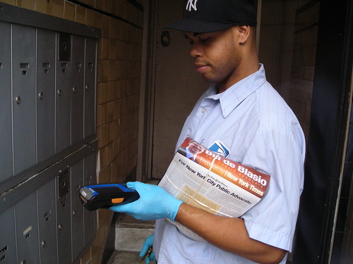
This postal worker had a fancy-schmancy device with a touch screen sensor, and he was kind enough to let me snap a shot of him using it.
 
Debateable as to whether it's "really" a sensor, but it seemed like maybe these bells could qualify as a sensor to the door's motion.

 
At St. Vincent's Hospital, the ER doors were equipped with motion sensors to open at a moment's notice.

 
Meanwhile, New York's new parking meter slash computers provided this guy with a satisfying button press.

 
This restaurant employee uses a touch screen sensor all day, and is damned excited about it!

 
Finally, I arrived to pick up my laundry and noticed this load in progress: it's using a sensor to measure water levels before it starts to spin.

 
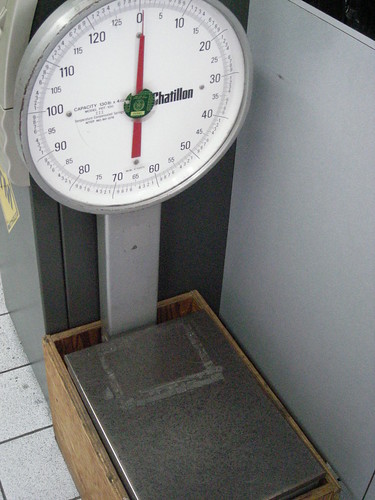
This scale is a sensor for laundry weight, and how much I'm going to be fleeced for keeping clean!

 
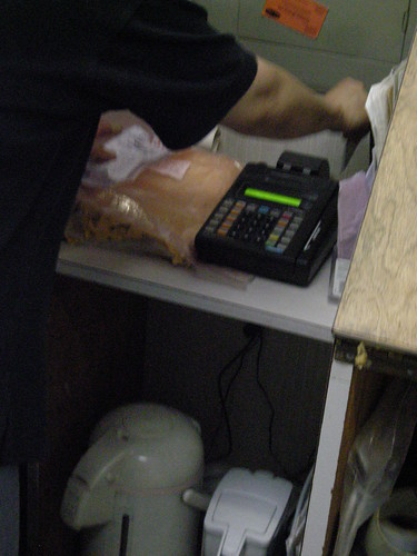
The credit card machine has two sensors:  one to read the magnetic stripe on the card...

 
...and the other to enter data via the key pad.

So I concluded my sensor walk:  fresh laundry in hand, and a new and unique perspective on my daily route home.

I Am Jack's Applications Presentation

Our Group (Group 2!) had the distinct privilege of being one of the first two to present in Red's Applications class.  We had to come up with a reaction to the Vito Acconci's presentation last week, and the video above is where it's at.  Themes we tackled included the difficulty of connection, connection as a universal challenge, and connection over technology.  Check it out above - thanks to all our super accommodating subjects!

Monday, September 14, 2009

Sol Lewitt At Columbus Circle

 
The Architect's Newspaper Blog has a nice mention of a Sol Lewitt installation that was unveiled yesterday at the Columbus Circle subway station.  Seems like a prime candidate for an ITP field trip!

Sunday, September 13, 2009

Medical Data, Trending, And Visualization

Wired has a pretty nice piece about aggregate medical data trending, and some pretty solid visualizations to go along with it.  Definitely worth a look.

Reactions To "As We May Think"

Finished up reading Vannevar Bush's "As We May Think" from the 1945 Atlantic, and have to say it was pretty entertaining.  Everything about the article is quaint, from the tone, to the ridiculously involved solutions to problems that have since ceased to even exist.  That being said, Bush's insight is remarkable, and he truly offers an amazing amount of foresight in regard to the problems that would be facing the world of information technology in the coming decades.

One interesting component of the article is how evident it is that it was written pre-transistor.  Almost all of Bush's solutions center around vacuum tubes and microfilm as the innovations of the day.  This leads them to be surprisingly involved, and often overly complex.  By contrast, the transistor enabled many of his innovations to be implemented in simple and beautiful ways.  It's yet another clear reminder of just how much the transistor transformed the climate of technology.

Saturday, September 12, 2009

Hello World.


Welcome to the first in a horribly large number of posts in, around, and about, the life of a student at Tisch's Interactive Telecommunications Program.  The student in question is me, Patrick Proctor.  Here I'll be outlining my progress in the program, projects and coursework, and giving general perspective on anything that happens to suit my fancy. 

If you'd like to see what I'm up to outside of school you can check out my (painfully out of date) personal website, or the blog I run called Hippies Are Dead.  See you out there!