Showing posts with label video. Show all posts
Showing posts with label video. Show all posts
Wednesday, January 27, 2010
Pixel By Pixel: Analog Animation
For Pixel By Pixel we were asked to "make pixels" using an analog source for our pixel generation. I decided to use my shower tiles and dry erase markers to create a big-pixel scene. The scene (above) depicts a short span in the geological evolution of a land mass, including rain, erosion, volcanic activity, and growth.
In hindsight, I would have zoomed out more in order to have a higher resolution grid. I also discovered that while dry erase markers come right off of tile, the same is not true of grout. You live, you learn.
Thursday, September 17, 2009
Solving A Rubik's Cube, or, Exercises In Extreme Boredom
After a number of vested attempts (both in the intellectual and physical world) to inspire myself in the art of solving a Rubik's cube, I found myself completely uninspired and apathetic about the task. Solving the Rubik's is an exercise in algorithm repetition and color matching, neither of which particularly appeal to me.
While it may not appeal to me, it was nonetheless a requirement of my class to demonstrate how the cube could be solved, and I needed a solution to that problem. As such, for those who are truly interested in solving the Rubik's, I offer up these fine options:
- Watch the video above. It's step 1 in an extremely (almost an hour!) lengthy tutorial. I started nodding off on step 4, but if this really interests you, the tutorial is exhaustive and complete.
- Go to this link. It's a Rubik's solver where you input your cube configuration, and it provides you with a solution.
- If you're more code-minded, go here. It's the source code for the above mentioned solver, and should lend coders an algorithmic insight into solving the cube.
Tuesday, September 15, 2009
Physical Computing: Week One Lab
Week one of Physical Computing brought on two labs that were both largely associated with familiarizing ourselves with the environment we'll be working in all semester. Specifically bread boards, the Arduino microprocessor, and basic circuits. As such, the labs involved more hammering out the basics than they did pushing the boundaries. That being said, with the addition of my Applications presentation this week, I wasn't exactly heartbroken to have PComp go easy on my creative side.
 The first section of the lab consisted of familiarizing ourselves with the breadboards from our tool kit. While it's a pretty basic concept, it's still worth going over and comprehending. Basic points are as follows:
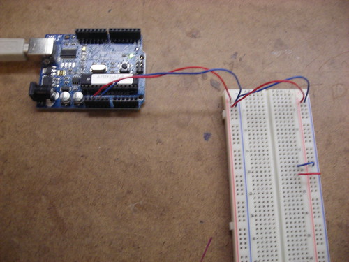 The next step was to actually power the board. This requires a 5 volt power supply and a ground. Above, you can see breadboard prepared and powered via the Arduino. Note that I've also wired two rows to use the power source: one row is a ground row, the other is a powered row.
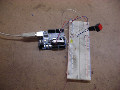 With the switch implemented, it was time to add LEDs to the board. The Arduino program would track the state of the switch, and modulate the LEDs accordingly. Above you can see a picture of the LEDs wired to the Arduino's digital outputs. The resistors in place assure a minimal load on the LEDs in order to increase their life.
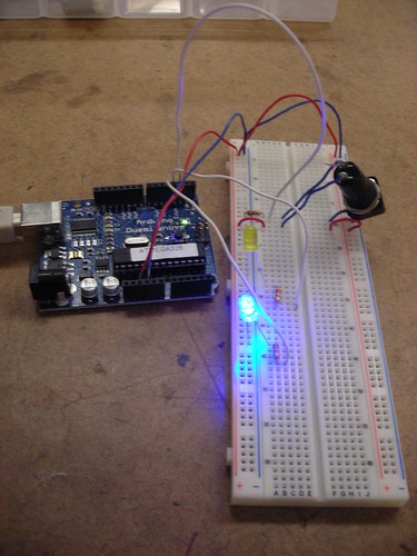
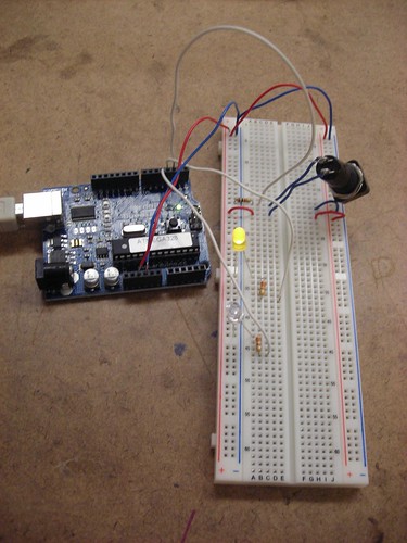 Finally, the setup was put to work: I compiled and uploaded the program from the lab to the Arduino, and proceded to enable it. Depending on the state of the switch, a different LED would be lit. You can see the two states above, and a video of the working mechanism below.
Once the basic switch setup was complete, we were entreated to contemplate other possible applications of basic digital I/O, particularly with regard to a combination lock. Upon considering this, most of my ideas drifted into the range of abstract or shape based locks. While most combination locks in the real world tend to be based around numeric key pads, it seems that one could be constructed based more soundly around interacting with a grid of switches that were either uniform, or based on a wide array of shapes and sizes. This would have the advantage of being more secure due to its abstract and spatial nature, and also being easier to remember for individuals who are already inundated with a large number of numeric codes in their lives. One example of this implementation that already exists in the digital world is the gesture based security in the Android mobile OS. However, there's no reason this same concept couldn't be applied to physical locks as well.
- The bread board consists of two parts: powered columns and isolated rows
- Each powered column is connected along the length of the board on the left and right sides. If these are connected to a power source and board, they then provide power to use in circuits.
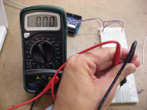
- The isolated rows go from top to bottom in the middle of the board, and are further isolated by a divider down the middle. This means for each row you have two sides that are isolated for use in a circuit. The photo above illustrates a multimeter validating the continuity of a single row.
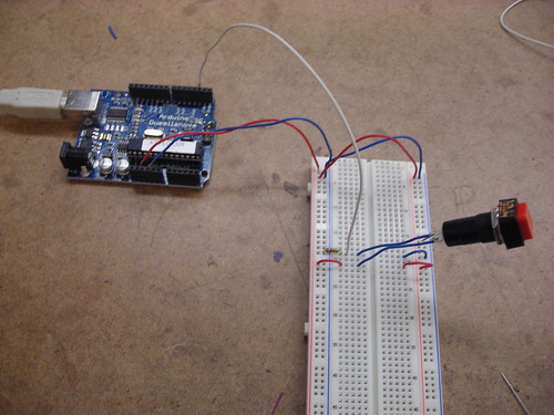
Once the board was powered, the next step was to add a switch. I decided to use a standard retail switch, and wire it to the left side of the board. The switch was connected (via the white cable, above) to a digital input of the Arduino, which would allow us to programatically track the switch's state. This required using two rows, and the addition of a resistor. The addition of the resistor ensures that the switches state will be reflected over the digital input wire, rather than just disappearing over the ground.
Once the basic switch setup was complete, we were entreated to contemplate other possible applications of basic digital I/O, particularly with regard to a combination lock. Upon considering this, most of my ideas drifted into the range of abstract or shape based locks. While most combination locks in the real world tend to be based around numeric key pads, it seems that one could be constructed based more soundly around interacting with a grid of switches that were either uniform, or based on a wide array of shapes and sizes. This would have the advantage of being more secure due to its abstract and spatial nature, and also being easier to remember for individuals who are already inundated with a large number of numeric codes in their lives. One example of this implementation that already exists in the digital world is the gesture based security in the Android mobile OS. However, there's no reason this same concept couldn't be applied to physical locks as well.
I Am Jack's Applications Presentation
Our Group (Group 2!) had the distinct privilege of being one of the first two to present in Red's Applications class. We had to come up with a reaction to the Vito Acconci's presentation last week, and the video above is where it's at. Themes we tackled included the difficulty of connection, connection as a universal challenge, and connection over technology. Check it out above - thanks to all our super accommodating subjects!
Subscribe to:
Posts (Atom)