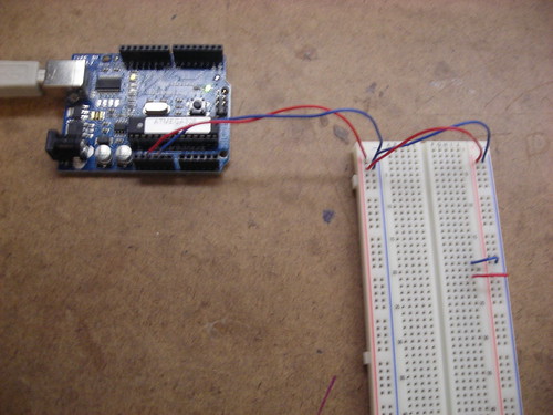
- The bread board consists of two parts: powered columns and isolated rows
- Each powered column is connected along the length of the board on the left and right sides. If these are connected to a power source and board, they then provide power to use in circuits.
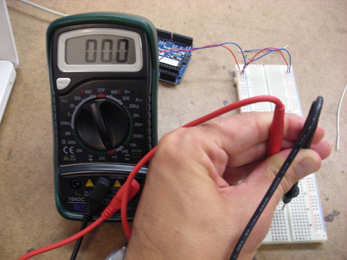
- The isolated rows go from top to bottom in the middle of the board, and are further isolated by a divider down the middle. This means for each row you have two sides that are isolated for use in a circuit. The photo above illustrates a multimeter validating the continuity of a single row.
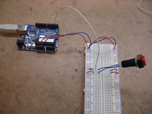
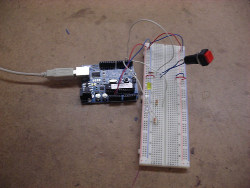
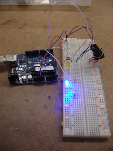
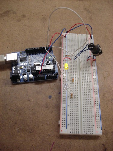
Once the board was powered, the next step was to add a switch. I decided to use a standard retail switch, and wire it to the left side of the board. The switch was connected (via the white cable, above) to a digital input of the Arduino, which would allow us to programatically track the switch's state. This required using two rows, and the addition of a resistor. The addition of the resistor ensures that the switches state will be reflected over the digital input wire, rather than just disappearing over the ground.
Once the basic switch setup was complete, we were entreated to contemplate other possible applications of basic digital I/O, particularly with regard to a combination lock. Upon considering this, most of my ideas drifted into the range of abstract or shape based locks. While most combination locks in the real world tend to be based around numeric key pads, it seems that one could be constructed based more soundly around interacting with a grid of switches that were either uniform, or based on a wide array of shapes and sizes. This would have the advantage of being more secure due to its abstract and spatial nature, and also being easier to remember for individuals who are already inundated with a large number of numeric codes in their lives. One example of this implementation that already exists in the digital world is the gesture based security in the Android mobile OS. However, there's no reason this same concept couldn't be applied to physical locks as well.
No comments:
Post a Comment